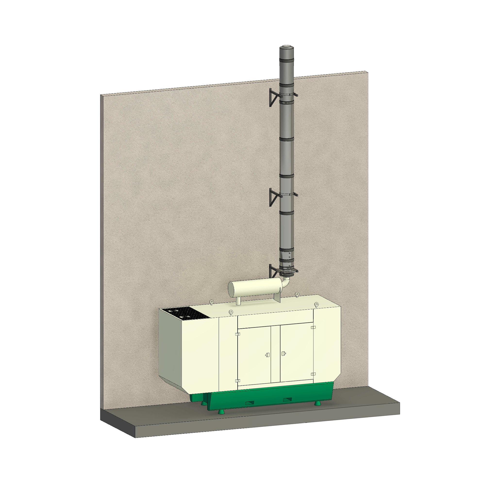
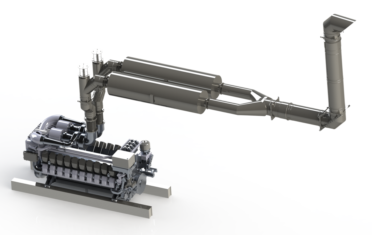
Generator and high pressure exhaust systems
DW-KL is a multifunctional, twin-wall insulated stainless steel flue system specially designed for high temperatures & high pressure, using a conical jointing system. Its main characteristic is that no sealing material is used but a permanent connection is established through a metal-to-metal joint without any gaskets.
Download DW-KL 25 Product Sheet
Download DW-KL 32 Product Sheet
Download DW-KL 50 Product Sheet
Download DW-KL Technical Manual
Can't find what you're looking for?
Contact usEnquire with us today
Product information
| DW-KL 25 316 | DW-KL 32 316 | DW-KL 50 316 | |
|---|---|---|---|
| MATERIAL | Interior Wall: AISI 316 Outer Wall: AISI 316 |
Interior Wall: AISI 316L Exterior Wall: AISI 304 |
Interior Wall: AISI 316L Exterior Wall: AISI 304 |
| INSULATION | High density rigid rock wool (120kg / m3) | High density rigid rock wool (120kg / m3) | High density rigid rock wool (120kg / m3) |
| WORKING TEMPERATURE | 600°C | 600°C | 600°C |
| FINISHING | Bright Possibility of painting in RAL colors (See special finishes here) Possibility of galvanized / zinc-plated exterior wall (only straight sections and deviations) |
Bright Possibility of painting in RAL colors (See special finishes here) Possibility of galvanized / zinc-plated exterior wall (only straight sections and deviations) |
Bright Possibility of painting in RAL colors (See special finishes here) Possibility of galvanized / zinc-plated exterior wall (only straight sections and deviations) |
| THICKNESS | Indoor wall: 0.4 mm – 0.5 mm – 0.6 mm (according to Ø) Insulation: 25 mm Exterior wall: 0.4 mm – 0.5 mm – 0.6 mm (according to Ø) |
Indoor wall: 0.4mm – 0.5mm – 0.6mm (depending on diameter) Insulation: 32mm (available with 25mm, check prices and codes) Outer wall: 0.4mm – 0.5mm – 0.6mm (depending on diameter) |
Indoor wall: 0.4mm – 0.5mm – 0.6mm – 0.8mm (depending on diameter) Insulation: 50 mm (available with 25 mm, check prices and codes) Outer wall: 0.4mm – 0.5mm – 0.6mm – 0.8mm (depending on diameter) |
| AVAILABLE DIAMETERS (mm) | 80 – 100 – 130 – 150 – 180 – 200 – 250 – 300 – 350 – 400 – 450 – 500 – 550 – 600 | 80 – 100 – 130 – 150 – 180 – 200 – 250 – 300 – 350 – 400 – 450 – 500 – 550 – 600 – 650 – 700 – 750 – 800 | 150 – 180 – 200 – 250 – 300 – 350 – 400 – 450 – 500 – 550 – 600 – 650 – 700 – 750 – 800 |
| CONNECTION SYSTEMS | Male-female conical connection with single connection clamp up to Ø125, and wide (2.0) from Ø150mm | Male-female conical connection with connecting clamp (2.0) | Male-female conical connection with connecting clamp (2.0) |
| FIRE RESISTANCE | Fire resistance classifications according to EN 13501-2: – EI180 ve (or– > i) T200 – EI120 ve (or– > i) T600 – EI120 ho (or– > i) T600 |
Fire resistance classifications according to EN13501-2: – EI180 ve (or– > i) T600 – EI180 ho (or– > i) T600 |
Fire resistance classifications according to EN 13501-2: – EI180 ve (or– > i) T200 – EI120 ve (or– > i) T600 – EI120 ho (or– > i) T600 |
| CE CERTIFICATE | 0036 CPD 9174 061 | 0036 CPR 9174 061 | 0036 CPR 9174 061 |
| EC CLASSIFICATIONS (UNE-EN 1856-1) | T600 – N1 – D – Vm – L20040 – G (70) T600 – H1 – W – Vm – L20040 – O (50) T200 – H1 – W – Vm – L20040 – O (20) T200 – P1 – W – Vm – L20040 – O (00) |
T600 – N1 – D – Vm – L20040 – G (70) T600 – H1 – W – Vm – L20040 – O (50) T200 – H1 – W – Vm – L20040 – O (20) T200 – P1 – W – Vm – L20040 – O (00) |
T600 – N1 – D – Vm – L20040 – G (70) T600 – H1 – W – Vm – L20040 – O (50) T200 – H1 – W – Vm – L20040 – O (20) T200 – P1 – W – Vm – L20040 – O (00) |